Filter Effects
The word filter comes from telephone and radio engineering: it decides which parts of a signal pass through and which are attenuated, according to frequency. Synthesizers and effects pedals later adopted those circuits, and the name came with them.
Almost every effects pedal contains a filter. A distortion pedal's tone knob, an EQ, the way delay repeats get darker: all involve filters cutting certain frequencies. But those filters usually just shape the tone. Once set, they stay put, so we do not usually call them "filter effects." The effects we do call filters often add two things:
- A pronounced resonance peak at a particular frequency, emphasizing the sound around it.
- A peak that moves, whether controlled by a wah pedal, swept automatically by an LFO, or opened and closed by your playing dynamics in an envelope filter.
That is why the previous article spent so much time on resonance: the "wah" of a filter effect is really a moving resonance peak.
Common Parameters
Type
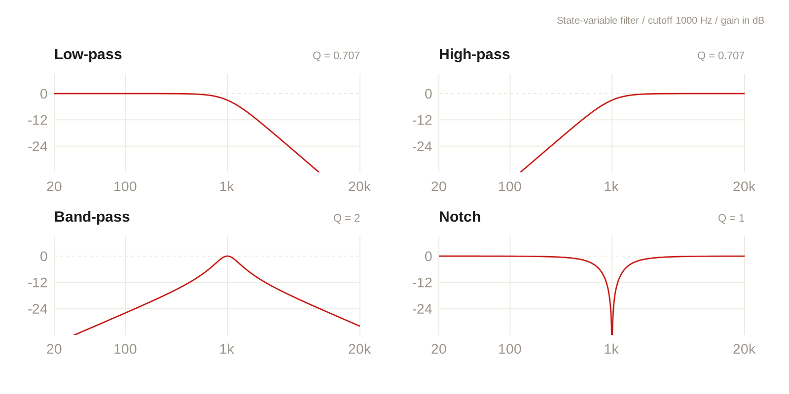
This determines which frequencies remain. A low-pass filter keeps the lows, making the sound darker and more muffled; a high-pass filter keeps the highs, making it thinner and brighter. A band-pass filter keeps only a band in the middle, a little like speaking through a cardboard tube. A notch filter does the opposite, cutting a band out of the middle.
Cutoff
This sets where the filtering begins. For a band-pass filter, the corresponding control sets the center of the band. In the resonator picture from the previous article, it controls the natural frequency. Moving a filter effect means moving this frequency setting. Strictly speaking, the resonator's natural frequency and the measured cutoff are not always identical; the relationship depends on the filter and its resonance.
Resonance (Q)
This controls how pronounced the peak near cutoff becomes. Turn it up and damping decreases: the peak gets taller and sharper, and the filter starts to "sing." Many filters can reach self-oscillation at high resonance settings. Effective damping falls to zero or becomes negative, allowing a tone to persist or grow even without an input signal. Nonlinearities eventually limit its amplitude, often producing a roughly sinusoidal tone. The principle is the same feedback discussed in the previous article.
Slope
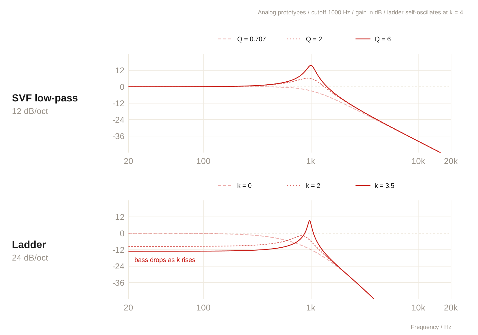
This describes how quickly frequencies fall away beyond cutoff, measured in dB/oct: how many decibels are lost for each octave farther into the stopband. Common slopes are 12 dB/oct and 24 dB/oct. The larger the number, the steeper the edge and the more obvious the filtering. The filter's structure usually determines this number. We will see it again with the SVF and ladder below.
Classic Filter Structures
State Variable Filter
The SVF design introduced by W. J. Kerwin, L. P. Huelsman and R. W. Newcomb in 1967 began as a solution to an engineering problem in integrated circuits. Its core is a chain of two integrators with feedback. The integrators' ability to accumulate a signal does the filtering, and three points in the loop provide separate outputs. Let us call them a, b and c.
input ─► Σ ─► a ─► ∫ ─► b ─► ∫ ─► c
         ▲              │         │
         ├── − k·b ◄────┘         │
         └── − c ◄────────────────┘
Integration means accumulation. High frequencies alternate rapidly between positive and negative, so much of their contribution cancels out; low frequencies change more slowly and accumulate further. Each point therefore leaves a different part of the spectrum:
- c: The signal has passed through both integrators, strongly reducing the highs and leaving the lows. This is the low-pass output.
- a: Subtracting c and k·b from the input removes the low and middle regions, leaving the highs. This is high-pass.
- b: This is a integrated once. The lows are already reduced at a, and integration reduces the highs too, leaving the middle band: band-pass.
One feedback loop gives the SVF low-pass, band-pass and high-pass outputs at the same time. Changing their responses takes just two parameters:
- Integration rate: This determines the frequency setting. Faster accumulation moves the dividing point upward, shifting all three responses together.
- Damping
k: This determines resonance. A smallerklets oscillation near the natural frequency persist longer, making the peak sharper and more vocal. At zero damping, the ideal loop can sustain a sine wave from an initial disturbance.
In the ideal design, these parameters are independent: changing the frequency does not change Q, and changing Q does not change the natural frequency. That makes the SVF especially useful for sweeping.
An analog circuit does not grow infinitely loud at self-oscillation because its components saturate, putting a ceiling on the signal. Digital implementations may add saturation such as tanh within the integrators to model that behavior.
Ladder
This is the structure behind the filter in classic Moog synthesizers: four first-order low-pass stages connected like the rungs of a ladder, with the final output fed back negatively to the input. Each stage contributes 6 dB/oct, adding up to 24 dB/oct. The edge is much steeper than a two-pole SVF's low-pass response, making the filtering more pronounced.
The four stages do more than set the slope. They also establish the conditions for resonance. In the ideal model, each stage contributes 45 degrees of phase lag at its cutoff. Four stages add up to 180 degrees, turning the subtraction in the feedback path into reinforcement at that frequency. Sound near that frequency grows on each trip around the loop, forming a resonance peak. More feedback makes the peak sharper; enough feedback produces self-oscillation. The tradeoff is that increasing feedback also reduces the lows. More resonance gives a thinner sound, one of the ladder's well-known characteristics.
Saturation is another part of its character. In an analog transistor ladder, the transistors naturally compress large signals. Push it harder and the sound gets rougher and warmer, while the resonance peak becomes more rounded. These qualities come from the circuit itself.
Four low-pass stages in series sound simple, but accurately modeling them digitally is more demanding. In an analog circuit, feedback acts continuously: input and output influence each other at the same time. A digital model works sample by sample, so a model without an added feedback delay may need the output to calculate the input, and the input to calculate the output. With saturation at every stage, this becomes a nonlinear problem. Accurate implementations often use iterative solvers, repeatedly refining an estimate until the error is small enough, though approximations and other approaches are also possible. The extra harmonics from saturation can also alias into harsh distortion, so oversampling is often needed. Together, these choices can make a ladder model considerably more expensive than a simple SVF.
Comb
A comb filter takes a completely different approach: a delay line instead of integrators. In the feedback version described here, a delayed copy is added back to the input, going around the loop again and again, just like the feedback in the previous article.
The difference is that it resonates at more than one frequency. With positive feedback, any frequency whose period fits an integer number of times into the delay returns in phase with itself and is reinforced. The result is a row of peaks at a fundamental and its integer multiples. The frequency response looks like a comb, which is where the name comes from.
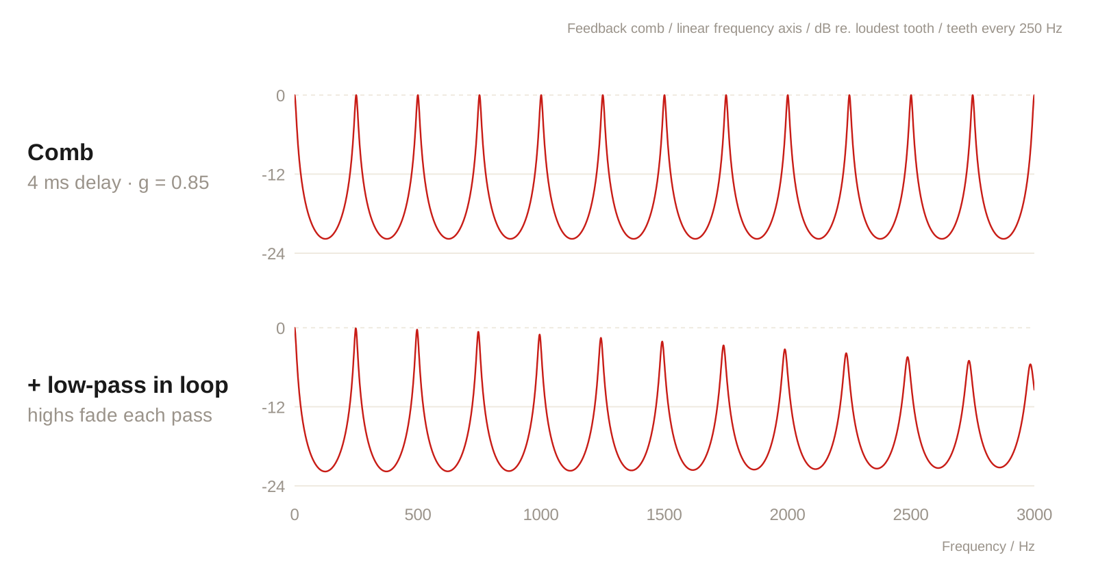
That evenly spaced row resembles the harmonic series of an ideal string or an open pipe, which helps explain the metallic, hollow quality of a comb filter. Delay time sets its pitch: shorter delays give higher pitches. Feedback sets how long it rings. Add a low-pass filter to the feedback path and each trip loses a little more high-frequency energy. The sound becomes less metallic and more string-like, with the highs fading faster, as they often do in acoustic instruments.
Phaser
A phaser is the exception in this section: its basic effect comes from notches rather than resonance peaks. It uses all-pass filters, which leave the magnitude of every frequency unchanged but alter their phase by different amounts.
Put several all-pass stages in series and mix the result with the dry signal. At certain frequencies, the phase has turned by half a cycle, opposing the dry signal and canceling it out to create notches. Move the all-pass frequency settings, and those notches move too.
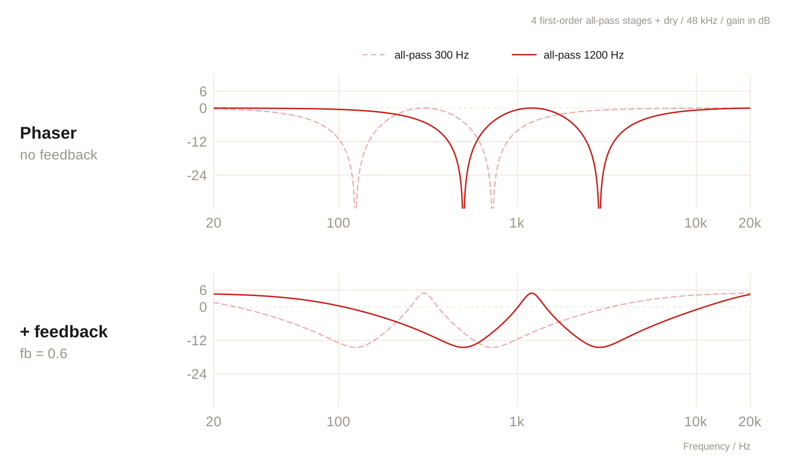
The result feels fluid and swirling, without the same resonant cry as a wah: the basic effect comes from phase cancellation. Many phasers add feedback to bring out peaks between the notches and make the effect more pronounced. Versions without feedback tend to sound softer and more transparent.
Twin
The previous article explained that the voice has more than one formant: several peak positions work together to define a vowel. The idea behind Twin is simple. If one moving resonance peak sounds like "wah," two peaks moving independently should produce something more complex and speech-like.
Here, two band-pass resonators run in parallel and move in different directions. One might open upward quickly with your playing while the other closes downward more slowly. As the peaks cross, the sound takes on a quality like changing vowels. It is not trying to model a particular vowel, just borrowing the mouth's ability to move several resonance peaks at once.
Driving the Filter
Wah
The most direct approach is to connect the frequency control to a pedal. A typical wah behaves like a sweeping band-pass resonator: press the toe down and the peak moves upward; rock back and it returns to the lows. Because your foot controls the motion, it can open and close freely with the rhythm and phrasing.
Auto
Replace your foot with an LFO, or low-frequency oscillator, and the cutoff sweeps back and forth automatically at a set rate. Rate and depth determine whether it feels like slow breathing or a regular "wah-wah-wah." The sweep can also be synchronized to the song's tempo.
Envelope
An envelope filter lets playing dynamics move the cutoff. In an upward sweep, playing louder opens the resonance peak higher. The first step resembles a compressor: a detector turns signal level into a smooth control curve called an envelope. A compressor uses that curve to control gain; an envelope filter uses it to control cutoff.
The curve usually rises and falls at different speeds. A fast attack follows the instant you pluck a string. A slower release lets the tail of the "wah" close gradually instead of snapping shut.
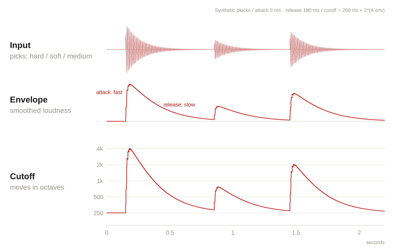
How the envelope moves cutoff matters too. We hear pitch intervals as ratios: 200 Hz to 400 Hz and 1000 Hz to 2000 Hz both sound like an octave upward. Mapping the envelope to frequency ratios instead of fixed Hz increments makes the sweep feel more even across registers.
Implementing EnvFilter
In a hardware envelope filter, character is tied to the circuit. The filter structure and the components that generate and apply the envelope largely determine its sound and feel. In software, those two parts can be designed separately, giving each filter structure the response that suits it best.
Once an algorithm is working, the first tests almost always reveal a few great settings: a particular sweep range, resonance level and envelope speed that make the peak move naturally. But those settings often occupy a small region. Change the phrase or nudge a control and the sound becomes too dull or too aggressive. Parameters also interact, and the level differences between structures can be substantial.
The part that really takes time is making the knobs stay within those useful regions as much as possible, wherever you turn them.
Parameters Interact
We hear the combined result of all the parameters, not each one separately. More resonance can make the sound louder and thinner as well as more vocal. As cutoff rises, the same resonance setting can sound harsher. Change the envelope speed and the peak spends a different amount of time in each region, changing the perceived resonance again.
Listening alone can make it hard to tell which parameter is responsible. My approach was to build a monitoring panel that displays cutoff, resonance and the envelope in real time, so I can watch while playing. Whenever something sounds unpleasant, I note the approximate settings at that moment. After enough examples, the boundaries become clear. I can then adjust the knobs' ranges and curves to avoid those regions.
Nonlinear Mappings
After enough testing, it becomes clear that one knob cannot always control just one parameter: changing one parameter moves the useful range of the others.
The solution was to let one knob move several parameters, each along its own curve. For example, turning TONE moves the sweep range upward, while resonance rises only gradually through the first half of the knob's travel and opens up more noticeably in the second half. That avoids excessive resonance in the lows and too little in the highs. Cutoff also moves in ratios rather than fixed Hz steps, keeping the sweep perceptually even across registers.
When the aim is a distinctly different character, I give it a separate mode. Each knob then only needs to cover the useful region within that mode, allowing finer control over its curves. To change character, switch modes. This gives each structure room to sound its best and makes it easier to combine structures later, producing sounds that no single one can make alone.
Gain Compensation
Different filter structures naturally produce different levels. With the same input, BP keeps only a band around the resonance peak and can sound much quieter than LP. A ladder loses low end as resonance rises, which can also lower its overall level. Without compensation, changing modes or turning a knob can cause level jumps. The effect seems to get stronger or weaker when part of the difference is simply loudness.
Each structure therefore needs its own gain compensation. The aim is consistent perceived loudness, rather than identical numerical peaks:
- Compensate for resonance: Higher resonance concentrates energy in a narrower band. Output gain follows the resonance setting to keep the peak's perceived loudness reasonably consistent.
- Compensate for drive: With saturating structures such as the ladder, more input drive also tends to mean more output level. An opposing output adjustment helps keep that increase under control.
- Adjust the dry/wet mix together: As BLEND changes the balance between the effect and the original signal, their gains also change to keep the overall level as consistent as possible.
Finally, every structure passes through an output limiter. The envelope moves the resonance peak quickly. If it briefly lines up with a strong harmonic, the level can jump. The limiter catches those sudden peaks before they reach the speakers.