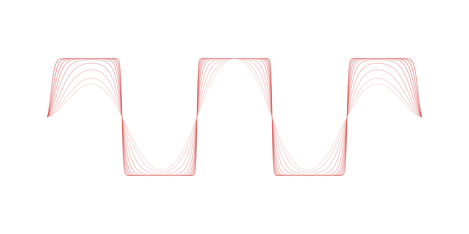
Overload
Every system that transmits, amplifies or records a signal has a range it can handle. Once the signal goes beyond that range, the output no longer faithfully follows the input. An amplifier's output is limited by its supply voltage, so the peaks get flattened. A digital system that exceeds the largest value it can represent simply cuts the waveform off. A camera sensor pushed past the brightest level it can record turns the highlights into flat white. When the shape of a signal is changed, or it gains components that were never there, engineers call it distortion.
Character
Distortion is usually a problem to avoid. But in the 1960s, musicians pushing their speakers to the limit stumbled onto a fuzzy, hairy sound, and from then on, "pushing parts to their limit" gradually became part of musical expression. Early music gear was also a small market. Few parts were designed specifically for sound; most were general-purpose parts that happened to be easy to buy at the time. Because of that, units of the same model could sound different depending on which batch their parts came from, which is the main reason vintage gear is so hard to recreate today.
Application
At its core, distortion reshapes a waveform within a limited range and creates a new series of harmonics. Early on, this change mostly came from "accidents" of circuits and parts. As technology advanced, how parts behave at their limits could be measured, analyzed, and recreated with circuits or digital processing. Distortion went from an accident to a deliberate way of shaping sound, and its use has spread from instrument tone to recording engineering.
Kinds of Distortion
In engineering, all of these are called distortion. In music they are usually grouped as dirty effects and roughly divided into Overdrive, Distortion and Fuzz. The boundaries between the three are blurry. I tend to pick one based on how dense and how soft or aggressive I want the sound to be.
Transfer Curves
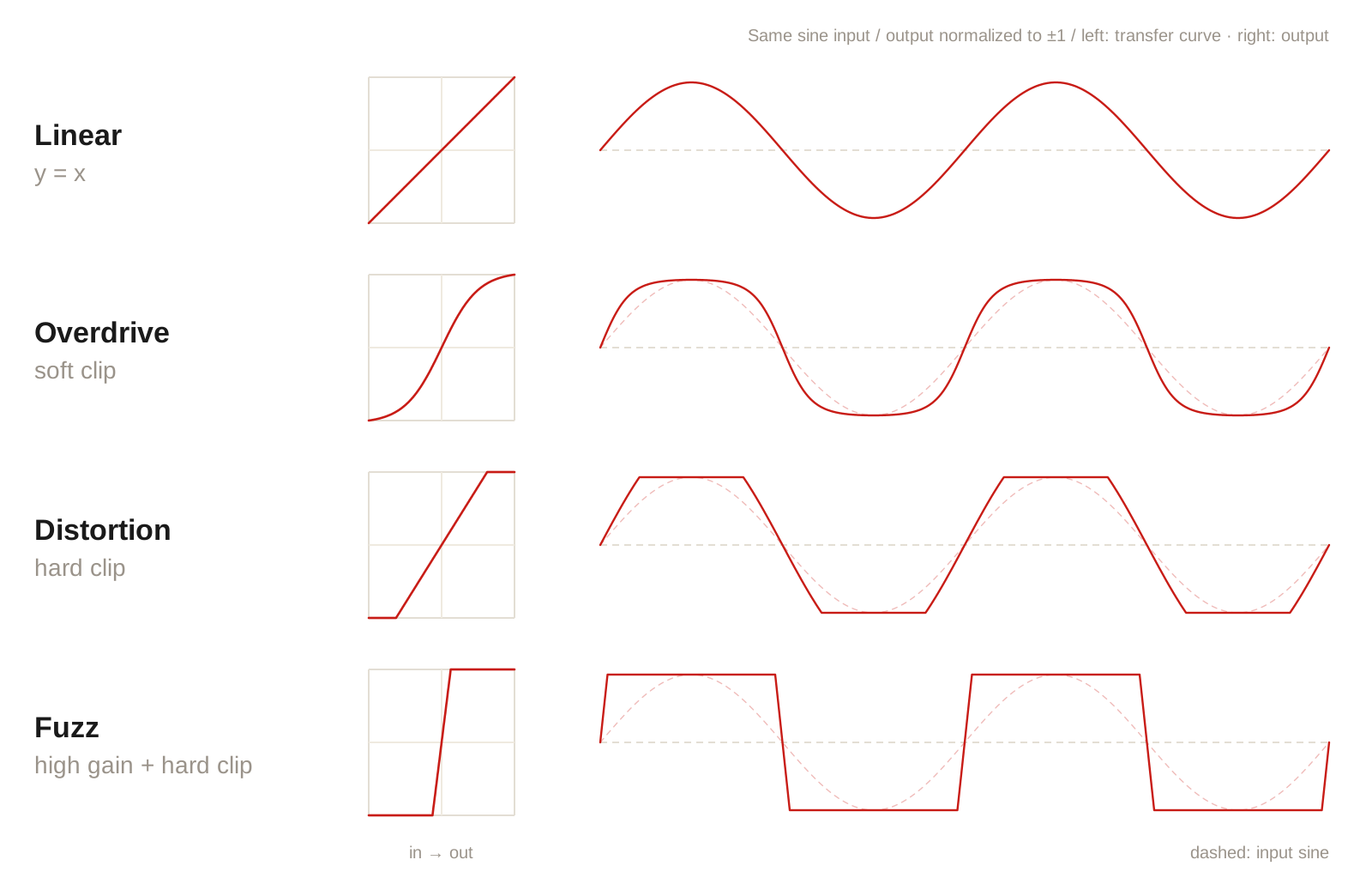
Plot how the input maps to the output and you get a transfer curve. Within its normal range, an amplifier's output grows in proportion to the input, so the curve is a straight line. Near the limit, the curve starts to bend and flatten, and the peaks get held down. This is clipping. In analog circuits, the curve comes from the components themselves; in digital, every sample is run through the curve once.
-
Overdrive: the curve bends more and more as it approaches the limit, so the peaks are gradually rounded off. This is called soft clipping. Small signals still sit mostly on the straight part of the curve, so light playing stays nearly clean; only larger signals push into the bend.
-
Distortion: the curve flattens earlier, so the peaks are cut flatter. This is called hard clipping. Most of the signal is held near the ceiling, so the dynamic range shrinks, the gaps fill in, and sustain gets longer.
-
Fuzz: the gain is so high that almost the entire waveform is pushed to the limit, close to a square wave. The tone is rough and hairy, and little of the original instrument's character survives. Because the waveform is close to a square wave, fuzz is often used to get sounds close to a synthesizer.
New Harmonics
Clipping changes the shape of a waveform, not how fast it repeats. Once the peaks are rounded or flattened, the waveform is no longer a pure sine, and the difference shows up in the spectrum as harmonics. Because the repetition rate hasn't changed, these harmonics all land on integer multiples of the original frequency.
These harmonics fall into two groups: even harmonics tend to sound warm, while odd harmonics sound harder and more "square". Their balance depends on the shape of the curve. When the top and bottom are clipped the same way (symmetric), only odd harmonics appear; when they are clipped differently (asymmetric), even harmonics appear as well.
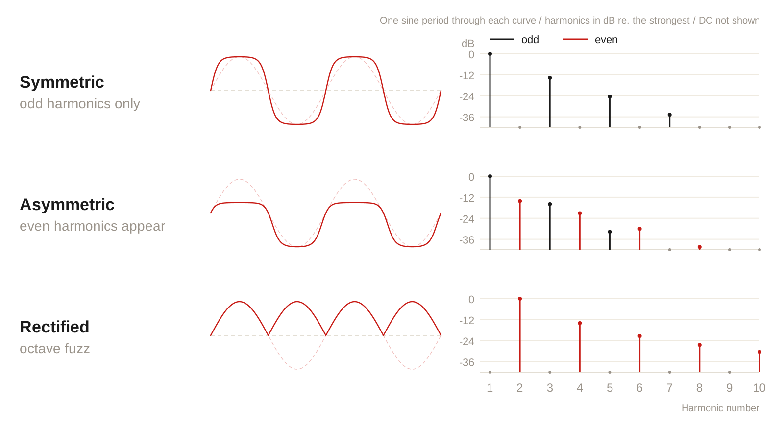
Push asymmetry to the extreme and you get octave fuzz. It doesn't just clip; it flips the bottom half of the waveform up, so both halves point the same way. The original frequency is then heavily reduced and almost only even harmonics remain. The strongest of them, the second harmonic, sits exactly one octave up, so it sounds as if an extra voice an octave higher has been stacked on top.
So the sound of distortion comes down to two things: how hard the signal is pushed, and the shape of the curve. The first decides how deep it breaks up; the second decides what the waveform turns into once it's pushed in.
Digital Distortion
The core of distortion is the transfer curve, which decides how the signal is mapped. In a digital implementation, some problems need extra handling, and some of the response analog circuits have naturally is missing.
Aliasing
Digital audio records a waveform as individual samples, and it takes at least two samples per cycle to represent a frequency. So the highest frequency it can represent is half the sample rate (Nyquist): 24kHz at 48kHz. Clipping, however, produces harmonics with no upper limit, and the sharper the curve bends, the higher they reach. Once sampled, a frequency above Nyquist looks exactly like some lower frequency. The system can't tell them apart, so it gets "folded" back into the range it can represent.
Harmonics just above Nyquist fold back to positions that are still very high and hard to hear, but the higher the harmonic, the further down it folds.
For example, at 48kHz, play A5 (880Hz): the 51st harmonic, 44880Hz, folds to 3120Hz, right where the ear is most sensitive.
The 55th harmonic, 48400Hz, folds to 400Hz, even lower than the note itself.
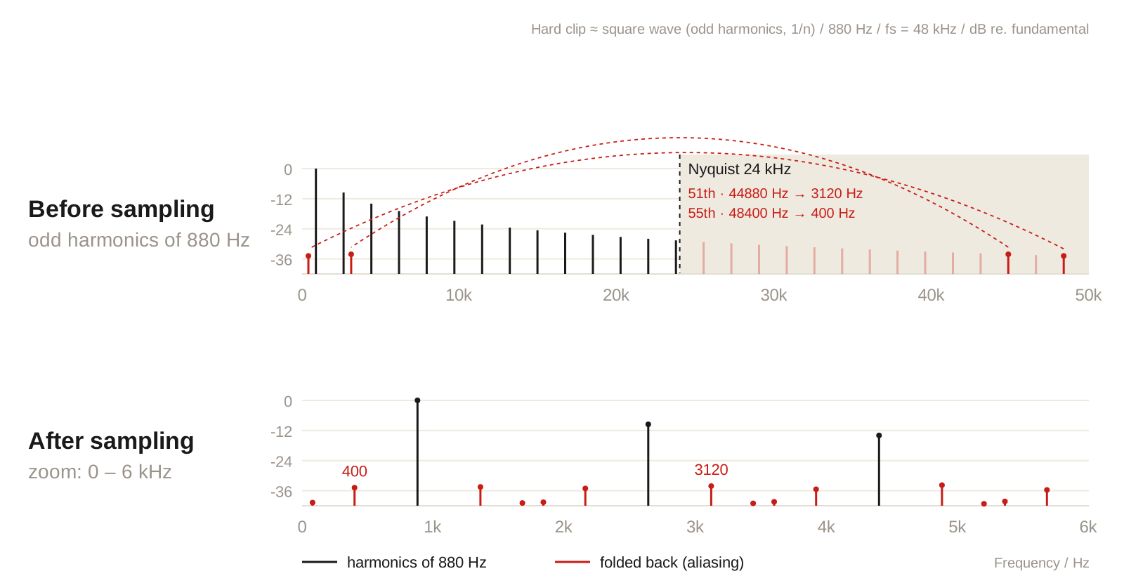
None of these frequencies are integer multiples of the original, so they are no longer harmonics but inharmonic noise. This is aliasing, and there are two common fixes:
Oversampling
Raise the sample rate, apply the distortion at the higher rate, then bring it back down. For example, at 4× (192kHz), Nyquist becomes 96kHz, so harmonics below 96kHz won't fold back. Before going back down to 48kHz, a low-pass filter removes everything above 24kHz. The only harmonics left to fold back are those above 96kHz, which are usually too small to hear. Higher factors are cleaner, but the processing cost grows with the factor, and the resampling filters can add a little latency.
ADAA (Antiderivative Antialiasing)
The usual approach only evaluates the curve at the sample points and ignores the sharp turns between them, which is exactly where aliasing comes from. ADAA instead computes the average of the curve between two samples (which requires its antiderivative). This smooths out the sharp turns before sampling, so less high-frequency content folds back. It needs no oversampling and is cheap, but it is less effective at high frequencies, slightly darkens the top end, adds half a sample of latency, and only works for curves whose antiderivative can be computed.
In practice the two are often combined: ADAA plus a lower oversampling factor (for example 2×) strikes a good balance between performance and sound.
DC Offset
As mentioned earlier, asymmetric clipping adds even harmonics. It also shifts the whole waveform up or down, adding a 0Hz component: DC offset. In analog circuits, the coupling capacitors between stages block DC anyway, so it is rarely noticed. Digital has no such protection, and the offset gets carried all the way through.
DC is inaudible, but it causes a few problems:
- It eats headroom: the waveform leans to one side and sits closer to
0 dBFS, so it clips more easily. - It affects later processing: if more distortion or compression follows, the shifted signal changes how they behave.
- Clicks when switching: the moment you bypass or stop playback, the signal jumps from the offset back to 0, producing a pop.
The fix is simple: put a very low high-pass filter (a DC blocker) after the distortion, for example at 5–10Hz, to remove the DC.
Computing the Curve
The simplest way to compute the curve is to run every sample through a fixed formula, such as tanh or a plain hard clip.
But a curve like that has no state, while a real circuit naturally changes with frequency and with the notes you just played, so by comparison the result sounds flatter and more lifeless.
To make the curve more interesting, you can try:
- Filters before and after the curve: shape the frequencies before the distortion so different bands are pushed into the curve by different amounts, then shape the tone after it.
- Simulating charge and discharge: capacitors in a real circuit charge and discharge with the signal, moving the bias and shifting the curve. For example, after a fuzz is hit by a large signal, the tail sputters and breaks up like a dying battery; a bias that slowly follows the signal level can produce a similar response.
- Simulating the whole circuit: methods such as Wave Digital Filters compute the interaction between resistors, capacitors, diodes and other components directly. This comes closest to a real circuit, but is also the most complex and the most expensive to run.
Building DIRTLAB
Distortion is very much a matter of taste. Once technical issues like aliasing and DC offset are handled, the rest is endless testing to find a curve you like, then shaping the tone with filters before and after it.
This bass distortion follows the usual approach: keep the low end clean, avoid mud, and preserve the dynamics of your playing. Different tones come from different modes, keeping the number of knobs as small as possible.
Input ─┬─ Clean: LPF ───────────────────────── CLEAN ─┐
       └─ Dirty: HPF → GAIN → Curve → HPF ──── DIRTY ─┴─ OUTPUT
SPLIT, OVERLAP
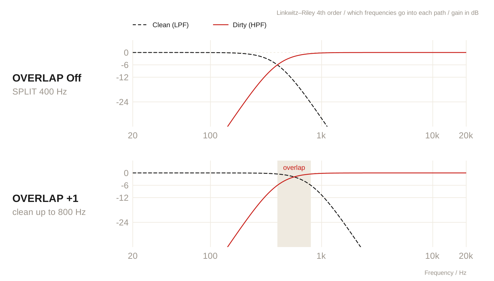
- SPLIT: the frequency where distortion starts. Signal below it never goes into the distortion.
- OVERLAP: how many octaves above SPLIT the clean signal extends.
For example, with SPLIT at 400Hz and OVERLAP Off, only the signal above 400Hz is distorted.
Turn OVERLAP to +1 and the clean signal extends to 800Hz, so the 400–800Hz range carries both clean and distorted signal.
If all you want is "distort everything above X", leave OVERLAP Off and just turn SPLIT.
GAIN, TONE
Both knobs act only on the distorted path and shape the sound of the distortion itself.
- GAIN: how hard the signal is pushed before it enters the curve, in other words how deep it goes into the bend.
- TONE: adjusts the balance of several filters, nonlinearly.
Because each mode's curve behaves differently, the same setting can sound stronger or weaker from mode to mode, so both knobs need to be calibrated per mode.
CLEAN, DIRTY, Output
This is essentially a Blend split into two level knobs, CLEAN and DIRTY.
When GAIN goes up, the distorted path naturally gets louder and needs DIRTY to compensate; with the two split, each side can be adjusted on its own,
and OUTPUT sets the overall level. Finally, a simple meter at the output warns when the level goes over 0 dBFS,
so the distortion you want isn't confused with the output actually clipping.